
A rectifier circuit turns alternating current (AC) into direct current (DC). Many electronic devices use this circuit to get steady power. The main parts of a rectifier circuit are:
-
A transformer lowers and separates the AC voltage.
-
Diodes let current move in one way, changing AC to pulsing DC.
-
Filters, like capacitors, make the DC output smoother for better use.
-
Protective devices help keep the circuit safe.
Knowing how these parts work together helps you build and fix electronic systems with confidence.
Rectifier Circuit Construction
A rectifier circuit has a few main parts. These parts help change AC into DC. You need to know what each part does. This helps you build a safe circuit. Let’s see what the main parts are and how they work together.
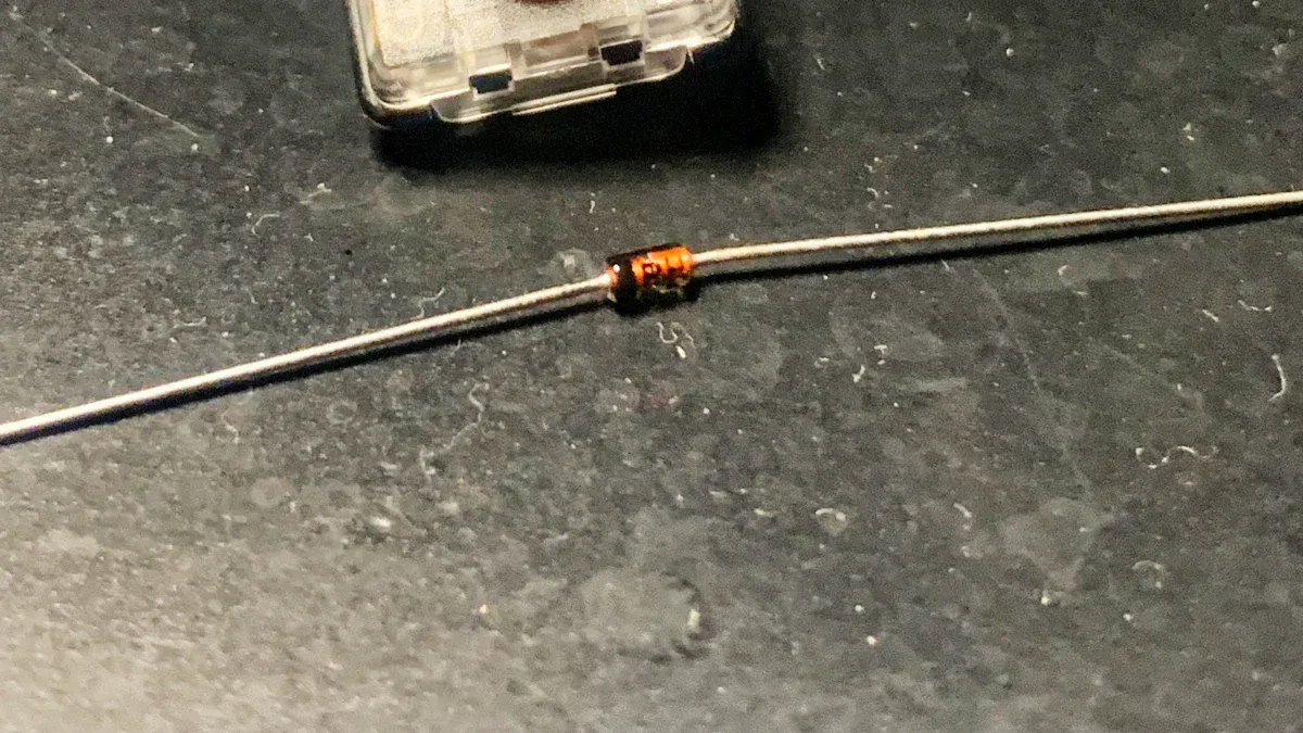
Diodes
Diodes are the most important part of a rectifier circuit. They let current move in only one direction. There are two common types: silicon rectifier diodes and Schottky diodes. Silicon diodes are good for high voltage and current. They have a steady voltage drop of about 0.7 volts. This does not change much with different currents. Schottky diodes work faster and have a lower voltage drop. This makes them good for high-frequency circuits.
Tip: Always check the voltage and current ratings of your diodes. If you use the wrong diode, it can get too hot or stop working.
Here’s a simple comparison:
|
Diode Type |
Key Features |
Best Use Cases |
|---|---|---|
|
Silicon Rectifier |
High voltage/current, good at high temperatures |
Power supplies, low-frequency circuits |
|
Schottky |
Fast switching, low voltage drop |
High-frequency, digital circuits |
You also need to watch for heat. Diodes can get hot. You might need heat sinks or other ways to cool them.
Transformer
The transformer changes the AC voltage to what you need. It also keeps you safe by giving isolation. Some transformers have extra windings or thick insulation. This helps them handle the job of changing AC to DC. A good transformer design cuts down on noise. It also helps the circuit work better.
-
Transformers with the right power rating do not overheat.
-
Special insulation and cooling, like oil or water, keep things safe.
-
A transformer with good isolation protects you from electric shock.
Note: Pick a transformer that matches your voltage and current needs. This keeps your circuit safe and working well.
Load Resistor
The load resistor goes at the output of the rectifier circuit. It controls how much current flows. For a 24 VAC source, you might use a resistor from 5.6 kΩ to 10 kΩ. If the resistance is low, more current flows and the output has more ripple. If the resistance is high, less current flows and the voltage is smoother. But it may not test the circuit like real use.
Pick a resistor that fits your project. If the resistor is too small, it can get too hot or make the voltage drop too much.
Filters
Filters help smooth out the bumpy DC from the rectifier circuit. The most common filter is a capacitor. It stores energy when the voltage goes up. It gives out energy when the voltage goes down. This fills in the gaps and makes the output smoother. Inductors can also help by fighting sudden changes in current. Sometimes, you use both in an LC filter for even better results.
|
Filter Type |
How It Works |
Best For |
|---|---|---|
|
Capacitive Filter |
Smooths voltage by storing and releasing energy |
Low-frequency ripple |
|
Inductive Filter |
Smooths current by resisting changes |
High-frequency ripple |
|
LC Filter |
Combines both for broad ripple suppression |
Wide range of frequencies |
Tip: A bigger capacitor makes the output smoother. But you can never get rid of all ripple. Always connect capacitors the right way.
Typical Arrangements
You can put these parts together in different ways:
|
Rectifier Type |
Main Components Arrangement |
Operation Summary |
|---|---|---|
|
Half-Wave Rectifier |
Single diode, AC supply, load resistor |
Diode works during the positive half, blocks the negative half. |
|
Center-Tapped Full-Wave |
Center-tapped transformer, two diodes, load resistor |
Each diode works on different halves; both halves of AC are used. |
|
Bridge Full-Wave |
Four diodes in a bridge, AC supply, load resistor |
Diodes work in pairs, so current always flows the same way through the load. |
You can add filters after the diodes and load resistor. This gives you smoother DC output.
Safety Reminder: Always use good wires and parts. Bad choices can make things too hot, drop the voltage, or even start fires. Check your connections and ratings before you turn on your rectifier circuit.
Working Principle
When you know how a rectifier circuit works, you can see how AC power changes to DC power for your devices. Let’s look at the steps one by one.
AC to DC Conversion
You begin with an AC input. This input is a wave that goes above and below zero volts. The rectifier circuit uses diodes to control which way current moves. Here is how the change happens:
-
AC Input Signal: The circuit gets an AC voltage that goes from positive to negative again and again.
-
Positive Half Cycle: At this time, some diodes turn on. They let current go through the load resistor. This makes a positive voltage at the output.
-
Negative Half Cycle: Other diodes turn on during this part. They keep the current moving the same way through the load. The output stays positive.
-
Filtering: A capacitor across the load charges up when voltage rises. It gives out energy when voltage drops. This smooths out the bumps in the output and gives you a steadier DC voltage.
Tip: If you add a filter capacitor after the diodes, it helps make the DC output smoother and cuts down on ripples.
Half-Wave Rectifier
A half-wave rectifier uses one diode to control current. When the AC input is positive, the diode acts like a closed switch. Current flows through the load resistor. You get a positive voltage at the output. When the AC input is negative, the diode acts like an open switch. No current flows, and the output drops to zero.
This happens every cycle. The output is a bumpy DC that only has the positive parts of the AC wave. There are gaps in the output where the voltage is zero during the negative parts.
In a half-wave rectifier, you use only half of the AC signal. This means the output has more ripple and is less efficient.
Full-Wave Rectifier
A full-wave rectifier uses two diodes with a center-tapped transformer or four diodes in a bridge. This setup lets you use both halves of the AC input. During the positive half, one set of diodes turns on and sends current through the load in one direction. During the negative half, the other set of diodes turns on, but the current still goes the same way through the load.
This gives you a steady bumpy DC output. The output frequency is twice as fast as the AC input, so the voltage never drops to zero. The result is a smoother and better DC output, especially if you add a filter capacitor.
|
Feature |
Half-Wave Rectifier |
Full-Wave Rectifier |
|---|---|---|
|
Output waveform |
Only one half cycle is rectified, with gaps |
Both half cycles are rectified, continuous output |
|
Current continuity |
Discontinuous (with gaps) |
Continuous (no gaps) |
|
Output frequency |
Same as AC input |
Twice the AC input |
|
Ripple |
Higher |
Lower, smoother output |
Note: A full-wave rectifier circuit works better. You get less ripple and more efficiency, so it is a better choice for most power supplies.
Characteristics
Efficiency
You want your rectifier circuit to give as much DC power as it can from the AC power it gets. Efficiency shows how well your circuit does this. You figure out efficiency by looking at the output and input power. First, find the DC output power. Multiply the DC output voltage by the DC output current. Next, measure the input power from the AC source. This part is hard because the current shape is not simple. Efficiency is output power divided by input power.
Tip: The best way to know efficiency is to measure it or use a simulation. Using just RMS voltage and current is not good enough. Rectifier circuits make current that does not have a simple shape.
If you add a filter capacitor, the DC output voltage changes. The output voltage is now the peak voltage minus half the ripple voltage. This helps you guess your circuit’s real efficiency better.
Ripple Factor
Ripple factor tells you how much AC "bumpiness" is left in your DC output. You want a low ripple factor for smoother DC power. To find the ripple factor, divide the RMS value of the AC part by the DC value of the output voltage.
-
A half-wave rectifier has a higher ripple factor. The AC part is about half the peak voltage.
-
A full-wave rectifier has a lower ripple factor. The AC part is about 0.707 times the peak voltage.
-
You can use an oscilloscope to check the AC and DC voltages at the output.
The ripple factor for a full-wave rectifier with no filters is about 0.483. Real circuits may be different, so always check by measuring.
Peak Inverse Voltage
Peak Inverse Voltage (PIV) is the highest reverse voltage a diode can take before it breaks. When the AC input goes negative, your diode faces this peak voltage. If the PIV is too low, the diode can break.
Pick a diode with a PIV rating higher than the biggest reverse voltage in your circuit. For a half-wave rectifier, the PIV is the same as the peak voltage from the transformer. In some full-wave circuits, it can be twice as much.
|
Diode Type |
Typical PIV Range (Volts) |
Example Model and PIV (Volts) |
|---|---|---|
|
1N4000 Series |
50 to 1000 |
1N4006: 800V |
|
1N5400 Series |
50 to 1000 |
1N5406: 600V |
|
Bridge Rectifiers |
200 to 1200 |
Various models |
|
Schottky Diodes |
Around 50 |
MBR150, MBR350 |
Always check the PIV rating before you choose a diode for your rectifier circuit. This keeps your circuit safe and working well.
Advantages & Applications
Benefits
There are many good things about using rectifier circuits in devices:
-
Rectifier circuits turn AC power into DC power well. This is needed for most electronics.
-
Bridge rectifiers use all of the AC cycle. This gives better efficiency and smoother DC.
-
You can use rectifiers in small gadgets and big machines.
-
These circuits give steady and low-cost power.
-
New materials like silicon carbide (SiC) and gallium nitride (GaN) make rectifiers work even better.
-
You can make modular rectifiers for different power needs.
-
Rectifiers keep sensitive electronics safe by giving steady voltage and stopping power swings.
-
You find rectifiers in solar energy, cars, phones, and many other things.
Tip: Modern rectifiers help your devices last longer. They give stable power and protect from voltage spikes.
Drawbacks
|
Rectifier Type |
Common Drawbacks / Limitations |
|---|---|
|
Half-wave |
Uses only half of the AC input, high ripple, low output, and more interference |
|
Full-wave |
Needs a center-tapped transformer, more parts, higher cost, and takes up more space |
|
Bridge |
Uses four diodes, which means more voltage drop and power loss, still needs filtering for smooth output |
|
All Types |
Always need filters to reduce ripple, and filtering gets harder and more costly as power needs grow |
Half-wave rectifiers waste power and make bumpy DC. Full-wave and bridge types need more parts and cost more. All rectifiers need filters to make the DC smooth for sensitive devices.
Uses
|
Rectifier Type |
Typical Applications |
|---|---|
|
1-Pulse |
Small battery chargers, simple power supplies, electronics kits |
|
2-Pulse |
Home appliances, small motors, medium power tools |
|
6-Pulse |
Industrial motor drives, large UPS systems, high-power DC equipment |
You see rectifier circuits in many places. They are in phone chargers, computers, LED lights, and electric cars. Factories use them in welding machines and big power systems. Rectifiers also help in solar panels and battery charging stations. You can pick the right type based on how much power you need and how smooth you want the DC output.
Rectifier circuits are important for giving your devices the steady power they need to work safely and well.
A rectifier circuit uses diodes, a transformer, and filters to turn AC into DC. Knowing what each part does helps you make safe circuits that work well. Start by learning where to put each part. Build your circuit on a breadboard. Test it with an oscilloscope to see how it works. You can find tips from Ultra Librarian for building circuits. Monolithic Power Systems has more advanced ideas. Write down what you do and always think about safety. The best way to get better is to plan carefully and practice building circuits yourself.
FAQ
What happens if you use the wrong diode in a rectifier circuit?
If you use the wrong diode, it may overheat or fail. The circuit might not work. Always check the voltage and current ratings before you choose a diode.
Can you build a rectifier circuit without a transformer?
Yes, you can build a rectifier without a transformer. However, you lose isolation from the power line. This can be unsafe. A transformer helps protect you and your devices.
Why does your rectifier circuit need a filter capacitor?
A filter capacitor smooths the DC output. Without it, you get a bumpy voltage with lots of ripple. Your devices may not work well with this kind of power.
How do you test if your rectifier circuit works?
Use a multimeter to measure the output voltage. You should see a steady DC voltage. If you have an oscilloscope, check for ripple. The output should look smooth.


